")

Welcome to leak detection technology
What is Pressure?

Pressure is defined as force per unit surface area. Where does this force originate from in a container filled with gas? Gas consists of a large number of particles (atoms, molecules) which are permanently in motion. When they collide with a surface, their recoil produces a force. Pressure is the sum of these forces produced by particles on unit surface area. The unit, in which the pressure is measured, is the Pascal (Pa = N/m2, Newton per square meter). Another valid unit of pressure is the bar (1 bar = 105 Pa). The standard atmospheric pressure (dry air at sea level) is 1.013 bar. This value comes from the older, and no longer used unit the Torr (760 Torr = 760 mm mercury column).
What is Vacuum?
Vacuum is produced by removing gas from a container. It is not possible to remove all the gas from a container by pumping; particles still remain in the container, producing a pressure. Zero pressure is therefore not possible in practice. The pressure relative to the absolute vacuum is called the absolute pressure. Thus there is still a positive pressure even in a good vacuum. Atmospheric pressure is about 1 bar absolute, and manometers which zero at atmospheric pressure and show negative in vacuum, measure a relative pressure against atmospheric pressure. Note that the negative values do not represent a negative absolute pressure.
A gas having a negative pressure relative to the atmosphere is called vacuum. By definition there are four levels of vacuum, depending on the size of the negative relative pressure:
Composition of Air
Air is a mixture of different gases. More than 99% of air consist of nitrogen and oxygen.
The rest are other gases.
Table 1
What is Partial Pressure?
Partial pressure is produced by a single gas in a mixture of gases. The table below shows the percentage composition of air. At a pressure of 1.013 bar the oxygen content is 21.224%, the partial pressure of oxygen in air is = 0.21224 bar or 212.24 mbar. The table can therefore be interpreted for partial pressures of the gas mixture in air
Table 2
The table shows the partial pressures of the gases in air in relation
to the Standard pressure of dry air at sea level = 1013 mbar.
Dalton's Law
Dalton's law gives the relation between the total pressure of a gas in a container and the partial pressure of its constituents.
Note that:
The gas mixture in a closed volume does not separate. In an air-to-helium mixture, the helium does not rise to the top of the container even though it is lighter than the other gases. This is because of the thermal speed of the particles there are inter-particle collisions in the gas as well as with the container walls and therefore always a mixing process, called "diffusion"
What is Gas?
Gas is a substance, where the particles (molecules and atoms) can freely move. In thermodynamic equilibrium these particles are uniformly distributed in space, so that the pressure, partial pressures and gas composition are the same at all points of the container.
A solid is a substance, the particles are fixed in their positions, they can only vibrate and rotate. A liquid is a substance, where particles can freely slide on each other but cannot separate from each other, hindered by intermolecular forces.
What is Vapour Pressure?
When the pressure above a liquid is reduced at constant temperature, it evaporates and the resulting gas is called a vapour. This vapour, like other gases, has a pressure called vapour pressure. The vapour can become a liquid again. This is called condensation. All vapours have a saturation pressure which is the pressure of the vapour in equilibrium with its liquid. When the pressure in a system is higher than the saturation pressure, the vapour condenses, causing the pressure to return to the saturation value. Vice versa, as long as there is still a liquid in the system, the pressure cannot be reduced (by pumping) lower than the saturation pressure, because the liquid continues to evaporate.
In a container, in which a liquid and its vapour are present and the pressure is equal to the saturation vapour pressure, evaporation and condensation occur simultaneously. Water and its vapour pressure in vacuum systems need our special attention, because water is always present as humidity in the air and water is difficult to remove from vacuum systems.
We call gases vapour, when they can condense at normal temperatures. Strictly speaking all gases can condense, it depends only how much the temperature is reduced.
Vapour pressure of water at different temperatures.
Table 3
Vapour pressure of some liquids at 20° C
Table 4
What is mean free path?
The mean free path (MFP) is the average distance which a molecule of a gas- or vapour travels before it collides with another molecule. At high vacuum, these distances become very large, so the particles collide only with the walls of the vacuum chamber.
The mean free path is proportional to the pressure. At atmospheric pressure the particles collide every 10 thausandths of a millimetre, but at a pressure of 109 mbar they collide only after 68 km. The following formula gives the mean free path for air at 200C at pressure P mbar.
The mean free path for some gases at 20° C and different pressures
(in mbar)
Table 5
1 nm [Nanometer] = 10-9 m
Avogadro's Law
What is a Mole?
A Mole (abbreviated to "mol") is a unit of quantity. The definition is:
The weight of each gas in a volume of 22.415 litres (at 0°C and 1,013 bar) is equal to the relative mass of one molecule of this gas.
Example: 1 mol Helium = 22.415 litre has a weight of 4 gm.
Units of quantity can be expressed in different units:
The characterisation of an amount of gas as p x V-value is mostly used in vacuum technology.
What is a leak rate?
A leak rate is an amount of substance, which passes in a certain time through a leak. As we have seen, there are several units for quantity, so the leak rates can also be expressed in different units. The symbol for the leak rate is "q".
Normally used are:
Avogadro´s Number
The relative masses of molecules
In the past these masses have been called "atomic weight or molecular weight", but this was misleading, because these numbers are only ratios between atoms or molecules.
The relative mass of molecules M (also called molar Mass) at SI-units is defined in kg/kmol. One hypothetical standard atom has the relative mass of 1/12th of the 12 C atom. The relative mass of a Helium atom is then:
or
M = 4 g / mol
Boyle's Law
When the volume of a gas is decreased (for example by a piston), the pressure increases in the same ratio, if the temperature does not change. Compressing the volume to a half of its size doubles the pressure.
also well known as:
When a vacuum is produced and the pressure is decreased by a large amount, the gases expand to very large volumes. This occurs also with contamination on the inner walls of the vacuum chamber, which evaporates (for example fingerprints).
with equal numbers of molecules (temperature kept constant)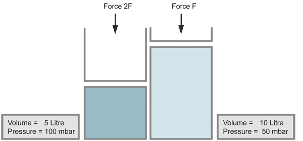
for the same number of molecules (constant temperature)
Charles' Law
The volume of a gas changes with temperature if the pressure is kept constant. When the gas becomes colder, the volume decreases. As it becomes warmer, the gas expands.
T in Kelvin (see scale of absolute temperature below).
When the temperature doubles, the volume increases similarily by the factor of 2, provided that the pressure stays constant.
with equal numbers of molecules and constant pressure
With a closer look at Charles` law, one can find a more detailed relationship between temperature and volume, known as the law of Gay-Lussac: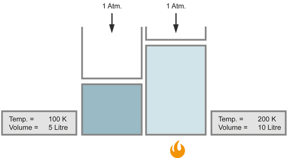
The Law of Gay-Lussac
When the temperature of a gas changes from 0°C by one degree, the volume changes by 1/273 of the original value:
or
From this law, Lord Kelvin founded the absolute scale for the temperature, in which 0 Kelvin = absolute zero = 273.15 degrees Celsius.
in Kelvin [K]
The above three law´s combine to give the universal gas law:
The universal Gas Law
Greek ν(Ny) is the symbol for the quantity in mol or kmol.
The universal gas law is not restricted like Charles´, Boyle´s and Avogadro´s laws.
The temperatures in Charles law and in the universal gas law are inserted as absolute temperatures in Kelvin.
The Universal Gas Constant
1 J (Joule) = 1 Nm = 1 Ws
For calculations, the following, equivalent values are often used:
Individual gas constants for some gases (J/kg x K)
If many calculations are made for the same gas, it is often easier to use the individual gas constant Ri
The greek alphabet
The Individual Gas Constant
If the universal gas constant is divided by the relative mass number (M) of the molecule of the gas in question, the result is the individual gas constant Ri for this gas.
Viscous Flow
At pressures above about 0.01 mbar the gas particles react more or less as fluids. The particles are very close to each other, so they collide more with each other than with the container walls. If they are pumped or if there is a pressure difference, they flow like a fluid.
There are two different kinds of viscous flow:
a.) Turbulent Flow and
b.) Laminar Flow.
Types of Flow
(Source: Leakage Testing Handbook, Prepared for Liquid Propulsion Section, Jet Propulsion Laboratory, National Aeronautics and Space Administration, Pasadena, California)
In most cases in leak detection technology it is not possible to calculate accurately the kind of flow - it must be estimated. Of course there are formulae for calculation of the conductance for different pipes etc. All these formulae contain geometry factors (length, diameter etc.) but with leaks in normal practice, these factors are unknown.
Turbulent Flow
Turbulent flow, which involves eddy currents, occurs only in larger leaks and at higher pressure differences. With a high speed of gas, only leaks with turbulent flow emit a sound (whistle) and these can be searched with ultrasonic leak detectors.
The formula for the leakrate at turbulent flow is not given here since leaks with turbulent flow are so large and can be readily located and repaired. There is seldom a need for calculation.
Path of a single molecule in turbulent flow.
Laminar Flow
Laminar flow is defined as a parallel flow of molcules in a pipe, whereby the transverse distribution of the speed of the molecules is parabolic.
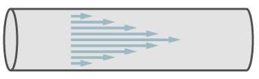
Path of molecules in laminar flow.
In the figure, the arrows symbolise the speed of the molecules. In the center of the pipe the speed is a maximum and it decreases towards the walls of the pipe.
The most wellknown formula for laminar flow is from Poisseuille. It describes the laminar flow through a straight tubulation with circular cross-section.
If one assumes that the geometry dimensions of a leak do not change during the period of measurement, the constants of the Poiseuille formula can be combined in one constant K:
Where K contains the following constants:
We can now see from this formula some properties of laminar flow: When the pressure difference across a leak changes, the leakrate changes with the square of the pressure according to the following formula:
From this we conclude that with increasing pressure in an object under leaktest a drastic increase of sensitivity can be achieved. On large containers which are filled with a search gas (for example Helium) to make a sniffer-test, a cost reduction can be achieved by increasing the inner total pressure, but reducing the concentration of the test gas. Of course the safety conditions for filling containers with pressurised gas must be followed.
Calculation of an example
An interesting example is calculated below, namely the difference in leakrate at the sniffer test, compared to a vacuum test. The leak geometry and the gas stay unchanged, also the pressure difference is 1 bar in both conditions. The difference is only: At the sniffer test the pressure conditions are 2 bar inner pressure against 1 bar (absolute) outer pressure, and at the vacuum test the outer pressure is 1 bar (atmosphere) and the inner pressure is zero bar (actually it is not zero. But for the calculation a 1/1000th of a bar is nearly zero).
| Vacuumtest |
|
| Sniffertest |
|
The leakrate at the sniffer-test is three times larger than at the vacuum-test, even if it looks like the same pressure conditions.
When the type of gas changes, the leakrate changes in inverse proportion to the dynamic viscosities of the gases.
Viscosity of some gases
As one can see, the difference of viscosity between gases is not so large, all are in the same order of magnitude.
Conversion of helium leak rate at laminar flow to leak rates of other gases
As can be seen from this table, the difference of leak rate of air is only 7.7% than helium, smaller than the accuracy of a helium-leakdetector. If we consider a leaktest with a helium/air mixture under laminar flow conditions, then the measured helium leakrate can be regarded as the same as the air leakrate. For example, in a test carried out with a 10% Helium / 90% Air mixture, the measured Helium leakrate is 10% of the total leakrate, which from the above table is:
(0.9 x 1.077) + (0.1 x 1) = 1.069
This shows an error of 6.9% taking the viscosity of air a 1.
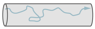
Molecular Flow
Molecular flow exists in small leaks and at low pressures. At molecular flow each molecule travels independently of other molecules. The mean free path is larger than the diameter of the leak capillary. Therefore it is possible, that a single molecule travels against the general flow direction, because molecules do not collide with each other, but only with the walls. Despite this fact, the general flow is in direction of the lower pressure. At molecular flow the molecules follow the partial pressure down gradient.
The figure shows the flow of a single molecule through a leak at molecular flow.
The formula of Knudsen for the leak rate at molecular flow is:
From the Knudsen´s formula one can see that contrary to the laminar flow, the leakrate follows linear proportion to pressure difference. To calculate a leakrate after a pressure change, the following formula is valid:
The dependency of the leakrate on molecular flow in relation to the type of gas, follows inverse proportion to the square root of the relative mass of molecules. Contrary to the laminar flow, a change of gas can make larger differences in leakrate (at constant pressure difference), as shown in the next formula:
Conversion of helium leak rate to air leak rate
The above formula with the relative masses of air and helium
at equal conditions of pressure and temperature
The air leak rate for molecular flow is a factor of 2.7 smaller than the helium leak rate. Data sheets of helium leak detectors often mention the equivalent air leakrate as well as the smallest detectable helium leak rate. This can be misinterpreted since the factor is only valid for molecular flow and not for the total range of measurement. Modern helium leak detectors can measure leakrates millions of times larger than in molecular flow. In conclusion, a helium leakdetector cannot measure air leakrates.
Conversion from weight leak rate to volume leak rate
In vacuum technology, the leak rate in general is described as volume leak rate (mbar.l/s). But there are industries which define the leak rates in loss of weight per year (g/a). The following example shows the conversion from loss of weight to volume leak rate (for constant pressure and temperature). Change to a different type of gas is also considered.
In an example from the refrigerator industry, the calculation for molecular flow leak rate becomes clear. Let us assume, that a refigerator manufacturer wants to check his products for a leakrate equal to or less than 0.01 g loss of the gas (R-12) per year. The correspondig volume leak rate is calculated via the mol:.
The relative mass of an R-12 refrigerant molecule is 121.
121 g of R-12 corresponds to 22.414 litre of gas at 1013 mbar und 00C, so that 0.01 gm R-12 = 1.85.10-3 bar.l that is 1.85 mbar.l R-12 per year.
1 year has 3.1536 . 107 seconds, then the R-12 volume leak rate is:
But this is not quite correct, because the mol is specified for the conditions of 0°C and 1.013 bar. The test takes place at room temperature, say 20°C. So we have to correct this result according to Charles´ Law (the pressure stays constant at both tests):
At molecular flow, when pressure and temperature stay constant, the corresponding helium leak rate is calculated as follows:
We remember: The dependency of the leak rate at molecular flow in relation to the type of gas, is inversely proportional to the square root of the relative mass of molecules.
This example is rarely used in practice. It was only chosen as a case of molecular flow. It shows that the helium leak rate in this case is factor 5.7 times higher than the R-12 leakrate. In practice, the required leak rates for refrigerators are in the range of 1 to 5 gm per year. These leakrates are already in the range of transition or laminar flow.
Conversion of helium leak rates at molecular flow to other gases
Note that the leak rate in molecular flow varies as the cube of diameter, whereas in laminar flow it varies as the fourth power. The leak rate for molecular flow in relation to the type of gas is inversely proportional to the square root of the relative mass of molecules (see formula of Knudsen).
Transition flow
There is a gradual transition from molecular to laminar flow which can be interpreted as both flows are present simultaneously or: at the entrance of the leak the flow is laminar which gradually changes, till at the end of the leak it is molecular flow.

The path of one molecule in transition flow. It shows collitions with the wall and with other molecules.
The mathematical description of this condition is difficult. There are some formulae available, all of them have some restrictions. The most simple formula is from Burrow. He combined the formulae for laminar and molecular flow.
This formula can be used for rough calculations, if one takes the geometrical dimensions of an idealized leak capillary with round cross section and length much longer than diameter. One has to estimate, if molecular or laminar flow predominates and use the formula of Poisseuille or Knudsen, to calculate the dimension of the idealized leak.
The Response Time
The response times mentioned on datasheets and specifications of leak detectors are the individual response times of the leak detectors without any test piece connected, or with just the reference leak connected and are valid only for leaktests with test pieces with very small volumes. The response time of a test arrangement is given by the volume divided by the effective pumping speed of the used pumps:
The following formula describes the increase of the leak rate signal:
and the following formula describes the decrease of the signal:
Example: Integral leak test on a heat-exchanger
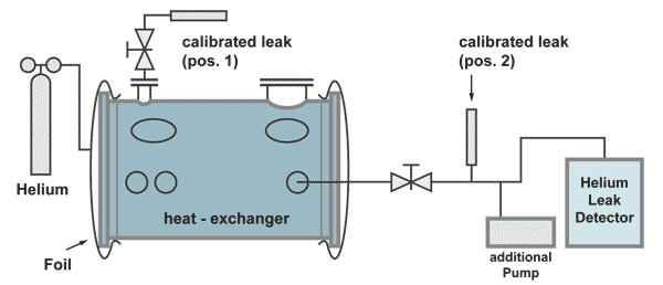
The effective pumping speed is the speed at the flange A of the heat exchanger (total pumping speed of the two pumps, reduced by the flow resistance of the pumping line).
The response time in this case is:
For the leak rate signal to reach almost its end value, a waiting time of 5 time constants is recommended. (see the following table). Therefore, after the volume under the foils is filled with 100% helium, a waiting time of around 18 minutes and 23 seconds is necessary, before the leak rate reading can be taken.
The size of the leak rate signal after tn time constants in %
The calibrated leak at position 2 is positioned before the pumping line divides between the additional pump and the leak detector. This is necessary to have a correct calibration. Part of the helium of the calibrated leak is pumped by the additional pump as is also with helium comimg from a leak in the heat exchanger.
The calibrated leak at position 2 has the following properties:
| Advantage: | The leak detector can be calibrated without helium coming into the heat exchanger, therefore not producing a background signal and calibration can be done in a short time. |
| Disadvantage: | The responsetime can only be calculated. |
The calibrated leak at position 1 has the following properties:
| Advantage: | The time constant can be measured by an extra experiment |
| Disadvantage: | The calibration of the leakdetector takes a long time, because for the increase of the helium signal as well as for the decrease (to pump away the background helium) at least 5 timeconstants are necessary. |
Remark:
Long response times, even longer than 18 minutes in this case, do not matter for the correct test result. But to localize a leak, response times of seconds are necessary. So this example shows the importance to watch the time constant during a search gas leak test
The Diffusion of Gases
The spread of one gas into another gas is called "Diffusion". Of course diffusion happens also with fluids, but here we are interested in diffusion of gases. Under equal conditions, light gases diffuse faster than heavy gases. The diffusion of gases is inversely proportional to their relative molecular mass.
Graham's Law of diffusion of Gases
(D = Diffusion coefficient, M = relative molecular mass)
Diffusion-Coefficients of some gases
at 0°C and 101.3 kPa
[mm2/s]
Note: Helium has the largest diffusion coeffcient
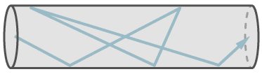
Example: Diffusion of Search Gas in Air
The diffusion of one gas into another at atmospheric pressure is relatively slow (and even slower at higher pressures). This requires special attention when test pieces are filled with search gas for a sniffer test. With long tubes with closed ends, the search gas cannot bypass the air which is in the test piece as far as the end of the tube. This air cushion can remain there for some time, before it is mixed with the other gases by diffusion. A leak, which happens to be at this end of the tube, may not be detected by the sensor, which is only sensitive for the search gas.
To avoid this problem, test objects should be evacuated, prior to filling with searchgas. Not a very good vacuum is needed. The diffusion speed increases with decreasing pressure. This can be explained by the expanding mean free path and therefore less collisions. If a filling of 100% search gas is wanted, the evacuation down to a pressure of 1 to 5 mbar is good enough (1/1000 - 5/1000 of atmospheric pressure).
Permeation
Permeation is the passage of a fluid into, through and out of a solid barrier having no holes. The process involves diffusion through a solid and may involve many phenomena such as adsorption, dissociation, migration and desorption.
Permeation can have an adverse effect on helium leaktest when the leakrate specification is low and the test time long. One material needing special attention is Teflon. Helium has a high permeability through Teflon and helium leaktests on test pieces with Teflon seals are almost impossible.
Permeation does not have to be taken into consideration during routine leaktest, when the measurement occurs in too short a time to permit the influence of permeation.
It can be seen, that with Neoprene it takes about 2 hours to reach saturation, but already after 30 minutes there is a leakrate of 10-9 Pa x m3/s. The gasket dimensions used in determining the graph are:
sealing length = 25 mm
thickness = 5 mm
For a larger container with gaskets of a total length of 1 metre, these permeation rates are 2 x 10⁻⁷ Pa m3/s (2 x 10⁻⁶ mbar l/s). With natural rubber or silicon rubber the time to saturation is shorter.
Thus we learn from this that, for a vacuum leaktest helium should be sprayed on these gaskets only for a very short time.
Helium Bombing Test
The bombing test is a special leak test for small and previously hermetically sealed parts which have an internal cavity like transistors, diodes, microprocessors or small relays. It cannot be used on plastic covered semiconductors (permeation). To get helium into these test pieces which are already tight, a large quantity of parts are placed into a pressure chamber and this chamber (bomb) is filled with helium to a certain pressure.
On a leaking part, helium penetrates into it but not into leak tight parts. After a certain bombing time, the parts are placed (also in large batch) into a test chamber and this chamber (bell jar, test fixture) is evacuated by a helium leakdetector. If there is a leaking part in the batch (as indicated by the response of the leakdetector), the batch is divided and each division is retested. After several divisions, the leaking part is located.
The measured leakrate is not the real leakrate. During the bombing time, the part may be not filled to 100%, also, after taking the parts out of the bomb, there is a waiting time, until the part is being tested. During the waiting time helium is escaping already, and if the leak is large, all helium may have escaped before the part could be tested.
This shows that, with the bombing test only small leaks can be discovered. A second test for larger leaks is necessary. This second test in most cases is a bubble test. The parts are placed into a hot liquid. The air inside a leaking part expands and a bubble escapes.
The filling process of helium into a leaking part is not linear. As the pressure inside increases (i.e. the lower the differential pressure), the slower is the filling rate. So the filling rate as well as the outflow rate follow an exponential function.
The formula, which descibes this process is shown below:
(* the value, which would be measured, if the testobject would be filled with 100% He at atmospheric pressure).
This formula cannot be solved to L (the real leakrate). L can only be found by trial and error (Iteration). Therefore leakrate specifications in most cases specify the bombing time, the bombing pressure and the maximun waiting time for the quoted maximum leakrate.
The Bubble Test
The bubble test seems to be the oldest leak detection method at all. A container is filled with pressurized air and dipped under water. From a leak there will be some bubble emission, an easy method for leak location. To measure the leak rate is not impossible but needs collection of the bubbles, measure their volume and divide this volume by the measuring time. As easy it sounds, the bubble test needs some precautions when it comes to higher filling pressures. A container with gas at high pressure can burst or explode and injuries are possible. So a safety wall between test and operator and inspection via a mirror may be necessary.
Some containers to be tested are too large to be dipped under water. Here an alternative bubble test is used. The critical areas of the container (for example the welds) are moistened with a foam developing liquid. The use of liquids manufactured for just this purpose is recommended. They are delivered in spray cans and they develop a very fine and white bubble mushroom. A large leak may blow away any bubbles and therefore the test may be carried out with first a very low overpressure and only second with the specified pressure.
A variation of the leak test with a foam developing liquid is the leak search on a test object which is not a container and therefore does not have an internal volume (for example the bottom of a large refinery tank) where the welds must be tested for leak tightness. Here the welds are wetted generously with the liquid. Then a small bell jar with a strong window is placed on top of the wet weld. With a small pump the bell jar becomes evacuated. Some rubber gaskets keep the bell jar sealed to the bottom. Inspection of the weld through the window (having proper lighting) will show eventually developing bubbles.
One must be aware that these tests, as all visual leak detection methods, have a weak point. That is the human eye. It is not an exact measurement device and is due to make errors. Even an experienced operator, working with high concentration can miss a bubble.
The sensitivity limit of the bubble test is difficult to determine. Looking at a small area say 10 cm2 with a magnifying glass for the time of a quarter of an hour a bubble developing from a leak of 10-7mbar l/s can be detected. But if an operator has to inspect the welds of 500 tube ends of a heat exchanger, one can expect to see only bubbles coming form a leak of 10-4mbar /ls. Also the sensitivity changes with changing pressures.
On the seminar about tightness measurements and leak testing methods ( see under products) these methods are described in more details.
Leak Test with pressure changing methods
Leak tests with pressure changing methods do show the total leak rate of a test object, also called integral test. They do not show the location of the leak. The pressure changing methods can be divided into three different methods: the pressure decrease test, the pressure increase test and the pressure difference test.
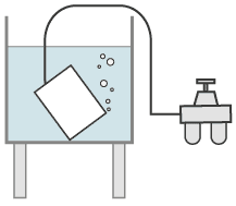
The pressure decrease test
At the pressure decrease test the test object is filled with a gas, in most cases pressurized air, to a pressure higher than atmospheric pressure. If a leak is present, the pressure will decrease over time. From the pressure difference between start and end of the test, multiplied with the volume of the test object and divided by the measuring time the leak rate can be calculated. 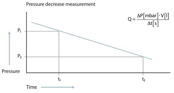
At the pressure decrease test the pressure must be measured with high accuracy and the temperature must be kept constant. Even a change of temperature of a few Centigrade can produce a pressure change larger than that from a leak
When the gas filling pressure is higher more than several bar above atmospheric pressure, a strength test of the container must be performed. This firmness test is done in most cases with water filling. The container is filled with water until no air is remaining. Then the pressure is increased in most cases to factor 1.3 higher pressure than the normal operating pressure of the container. If during this test a crack would happen only some water would be spilled. If the container would have been filled with gas, then the container can explode and make serious damage and injuries or even danger of life to human people.
Such a water pressure test can also work as a rough leak test. A small amount of water coming out of the container will make a distinct pressure change. Also during this test a change of temperature produces a change of pressure because the thermal expansion coefficient of water is larger than that of steel. After such a strength test the container must become completely dry before performing the leak test with gas filling. A small leak can block the gas throughput because water sticks inside the capillary because of its surface tension.
In general it can be said that this leak test procedure is good for small test objects. Objects with large volumes or large geometrical dimensions have easily failures in measurement mostly because of temperature changes It is possible that a large test object does have different temperatures on each end. If someone seriously has to plan such a test, he can contact me for discussion of failure calculations.
The pressure increase test
At the pressure increase test the test object first is evacuated. Then the pressure increase is measured over time. The disadvantage of the pressure decrease test, namely the difficulty to messure very fine pressure changes at a high total pressure is not so present with the pressure increase test, because the amount of gas at begin of the test is much lower and the pressure increase cannot become higher than 1 bar.
Of course at the begin of the test there is a non linear pressure increase coming from the degassing of the inner walls and this is mostly humidity. When the pressure has increased above the water vapour saturation pressure, the pressure change becomes a linar function. This makes it necessary to have a graphic plot of the measurement. Then from the linear part of the curve the leak rate again can be calculated from volume, pressure difference and time.
Pressure difference test
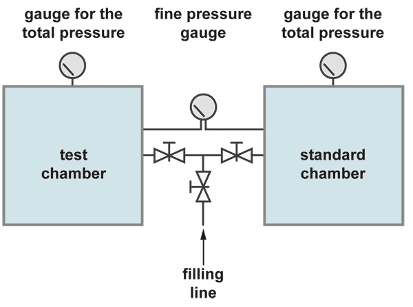
The integral leak test with the pressure difference method is the most accurate test but also some more complicated. The pressure in the test object is compared with the pressure in a standard container which is certainly leak tight. The fine pressure gauge has a pressure range of about 100 mbar full scale, while the total test pressure may be 10 bar.
Both container are filled slowly and simultaneously up to the test pressure. Care has to be taken that the fine leak rate meter is not stressed. After some waiting time for stabilisation of the pressure the pressure difference test can start. So it is possible to have a resolution of the fine pressure gauge of 1 mbar during a total pressure of for example 10 bar. There is also a better chance to overcome the temperature problem. If both containers are similar in dimensions they may change the temperature, if ever, in the same degree and in the same direction.. The leak rate is then calculated in the same manner from volume times pressure difference divided by the measuring time.
Short Introduction
The test for leak tightness with helium and helium leak detectors becomes more and more important. The practice of leak detection on heat exchangers is described in this article. Three possible methods are discussed.
The integral leaktest with vacuum in the volume around the tubes and helium at atmospheric pressure in the volume of the tubes
The preparations prior to the test, the correct procedure during the test, the pumpdown and the response time are discussed, also problems and suitable gaskets and seals. Problem solving for negative test are described.
The integral leaktest with helium pressure in the volume around the tubes and vacuum in the tubes
This test is sometimes necessary, when the volume around the tubes has had a helium filling in the past, for example for a leaktest with the sniffer probe. The changes in test conditions are decribed. Also the calculations of the leakrate according to pressure changes are discussed and the possibility of cost reduction by reducing the helium concentration as a result of pressure increase is pointed out.
The integral leaktest with helium pressure in the volume around the tubes and atmospheric pressure in the tubes
This test requires long waiting times and is used only, when other methods are not possible and when the safety conditions allow a higher testgas pressure in the volume around the tubes. The test is carried out by measuring the helium concentration in the volume of the tubes. The value of the leakrate must be calculated. The procedure of this test, the calculation of the waiting time as well as the leakrate are described.
General
In the past several different tracer gases have been used to find leaks and to measure leak rates, for example Ammonia or halogen gases. But since the leak test method with the tracer gas helium and the detection of this gas with a mass spectrometer was developed, all other methods became less significant compared to the superior sensitivity of the helium method. Also the measurement with a mass spectrometer ensures, that only helium and no other gases can influence the test.
Some properties of tracer gases
speed
path
conductivity
Leak Test with helium
Leak search and leak rate measurements with the tracer gas helium and sensing of this noble gas with mass spectrometer leak detectors has won such a large significance that this method can be marked as the most important leak detection method nowadays.
The Design Principle of Helium-Leak detectors
The following sketch shows the principle of a helium-leak detector, reduced to the essential components. 
Tracer gas leak location techniques
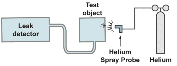
The vacuum method
The pumps built into the leak detector evacuate the test object. If, by spraying helium to the test object, traces of helium come into the vacuum, a helium partial pressure is produced, which is given by the amount of incoming helium and the amount pumped away by the pump. The spectrometer tube measures this partial pressure. The pumping speed of the involved pump is included as a constant to the measurement and multiplication of the measured partial pressure by the pumping speed gives the leak rate [mbar.l/s]. By calibration of the leak detector, this multiplication is done electronically and the reading of the meter is then calibrated in leak rate.
With a gas spay probe a fine helium beam is directed to the critical areas from the outside. If a leak is present helium is pumped to the mass spectrometer of the leak detector and rapidly displayed on the leak rate meter. The response time, which is a function of test object volume divided by the pumping speed, must be in the range of seconds. Longer response times make it difficult to locate the leak. With a fine movement of the spray probe is searched for the maximum helium signal. There is the location of the leak. It is recommended to start the leak search at the top of the system, moving slowly to the bottom.
Otherwise some helium could raise to higher positions and if there would be a leak a singal would be displayed, irritating the operator, who is pointing the probe to a much lower position.
The sniffer method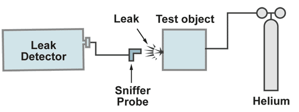
The test object is filled with the tracer gas with a pressure higher than atmospheric pressure. From the oustside a sniffer probe which is connected to the leak detector, is moved over the critical areas. If a leak is present, helium comes out and is sucked in to the sniffer probe and through that to the leak detectors mass spectrometer. The leak rate meter will show a display of the signal. When the maximum leak rate display is found, the leak is located. This method has two advantages and two disadvantages compared to the vacuum method. Sniffing for the leak location shoud start at the bottom of the test object and slowly move to the top.
1.) Advantages:
a.) The response time is only given by the lentgh of the sniffer probe, regardless how large the volume of the test object is.
b.) The sensitivity of the method can be increased by increasing the tracer gas pressure.
2.) Disadvantages:
a.) The leak rate cannot be measured exactly, because one never knows, if all the tracer gas escaping from the leak, is completely sucked in by the sniffer probe.
b.) The sensitivity of the test is limited by the helium content in the air (5 ppm), which produces a background
Integral Leak Test Methods
The integral leak test is the measurement of the total leak rate of the whole test object. It can be carried out with two methods:
1.) from the inside to the outside
2.) from the outside to the inside
This methods do not give information´s about the leak location.
Integral leak test "outside - in"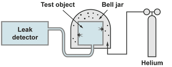
The test object is evacuated by the helium leak detector. The outside of the test object is covered by some envelope or bell jar which is filled with 100% helium. With a bell jar the 100% filling can be achieved by evacuating the bell jar prior to the helium filling. At an envelope, which cannot be evacuated because it is weak (for example some plastic foil) the 100 % filling can only be achieved by flushing helium in and measure at an outlet opening the helium concentration.
If a leak is present, helium will come in and will reach the spectrometer which then displays directly the leak rate. With this kind of measurement the responsetime is insignificant (contrary to the leak location techniques) Possible the leak rate signal will increase slowly. The operator has to wait until the leak rate meter shows a stable leak rate.
Integral leak test "inside - out"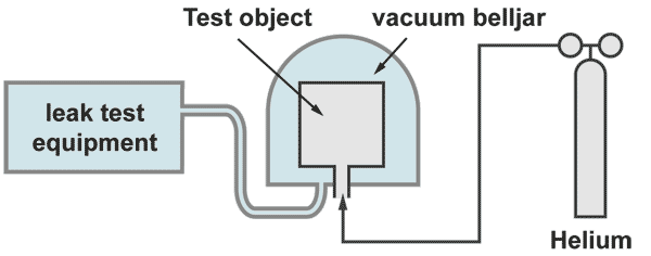
The test object is filled with 100% helium and placed under a belljar. The bell jar becomes evacuated by the helium leak detector. If a leak is present, wherever it is located, helium pures out and will be detected an displayed by the leak detector. The response time is given by the rest volume of the bell jar divided by the pumping effective pumping speed on the bell jar.
Large test objects, which cannot be placed under a bell jar, can be enbveloped by a plastic foil. With a sniffer probe the increase of the helium concentration under the foil is measured. Prior to the test the snifferprobe must be calibrated to measure helium concentration. This test can have long waiting times. The foil should be metalized for avoiding helium loses due to permeation. A detailed description of this procedure, including sample calculations, is given on the seminar on Leak Detection and leak test methods (see under products)
Leak detection with Hydrogen
In the past, leak detection with the search gas hydrogen was of little significance, because of the dangers involved with this gas. In the meantime a semiconductor sensor has been developed which can measure hydrogen concentrations down to 0,5 ppm. The hydrogen content in the atmosphere is also only 0,5 ppm (ten times lower than the background of helium). Therefore it becomes interesting to search for leaks with a test gas mixture of 5% hydrogen and 95% nitrogen. This gas mixture is neither inflammable nor explosive.
The use of hydrogen as a future source of energy has already initiated applications such as fuel cells, hydrogen motors etc. which are filled with & driven by this gas. Thus the use of hydrogen as a sensor is an ideal solution for leak testing. Mass spectrometer leak detectors can be calibrated for hydrogen, but a simpler solution is to employ the semiconductor sensor, which detects hydrogen without the need for vacuum.
For leak location with this method only the sniffer method is possible and for integral leak test only the method inside out is possible, as been described under helium integral test for large test objects.
Leak Test with Laser Beam
There also are methods to check for leakages by means of laser beams. A test object is filled with a tracer gas to a certain overpressure. The outside of the test object is scanned with a CO2 Laser beam. If the Laser beam meets this gas escaping through a leakage, then the electrons of this gas are activated to a higher energy level by the laser beam, i.e. one or more electrons of the gas molecules are transported on a higher trajectory. When falling back on the original trajectory this energy is released again. This takes place by emission of photons (a light lightning with a certain frequency [colour]).
These lightning´s are detected by a suitable sensor and synchronized with the scanning raster. On a picture of the test object, shown on a monitor, the leak location can be recognized.
Historical Literature about Vacuum-Technology
| Author | Title | published at: |
|---|---|---|
| Otto v. Guericke | Neue Magdeburger Versuche | VDI-Verlag, Düsseldorf 1968 |
| H. Ebert | Vakuum-Chronik | PTB Braunschweig 1977, ISSN 9341-6682 |
Historical Literature about Leak Detection Technology
| Author | Title | published at: |
|---|---|---|
| A.J.Dempster | A New Method Of Positive Ray Analysis | Phys. Rev. 11, 316, 1918 |
| A.O. Nier | A Mass Spectrometer for Routine Isoptope Abundance Measurements | Rev. Sci. Instr., 11,212, July 1940 |
| Thomas, Williams, Axd, Hipple | A Mass Spectrometer Type of Leak Detector | Rev. Sci. Inst. Vol. 17, 10, 1946 |
| A.O. Nier et al | Mass Spectrometer for Leak Detection | J.Appl.Phys. 18, 30, Jan 1947 |
| Nier, Stevens, Hustrulid, Abbott | Mass Spectrometer for Leak Detection | J. Appl. Phys. Vol. 18. 1947 |
| Ochert, Steckelmacher | Leak Detection Practice | Vacuum, Vol. II, No. 2, 1952 |
| Douglass, Charpentier | A Simplified Mass Spectrometer | Net. Symp. Vac. Trans. London, 1956 |
| Mongodin | l´Hélitest, Spectromtré de Mass Détecteur de Fuites. | Proc. 1st. Cong. Vac. Tech. Namur, 1958 |
| H.W. Drawin, K.Kronenberger | Ein neues, universell einsetzbares Lecksuch-Massenspektrometer | Vac. Tech. 8 H 5, 1959 |
| NN, Lab basses Press. 87 Rue A G | Helium Leckdetektor: Helitest | Zit. in Vak. Tech 12, H 7,138, 1959 |
| Cosutta, Steckelmacher | Lens mass-spectrometer leak detector | J. Sci. Instr. Vol. 37, 1960 |
| F. Kirchner und A. Benninghoven | Über ein doppeltfokussierendes Massenspektrometer | Vak. Tech. 12, H 7, 207, 1963 |
| G. Reich | Massenspektrometer mit hoher Partialdruckempfindlichkeit für Lecksucher | Trans 3, Int. Vac. Cong. Stuttg. 1965 |
| NN | L`Etancheite A Pierrelatte..("Diatron 18"), | Le Vide Nr. 108, 11 ff, ca 1965 |
| A.H. Turnbull | Leak detection and detectors (20th Century L.D.) | Vacuum 15 / 1, 3 ff, 1965 |
| Bültemann | Streuionenunterdrückung beim Gasdetektor | ME4, MAT, Lab.-Ber., Fr. Krupp, |
| W. Becker | Anordnung zur Lecksuche nach dem Massenspektrometer-Prinzip | Auslegeschrift 1648648 D.Patentamt |
| W. Becker | Erhöhung der Empfindlichkeit des He-Lecksuchers durch Verwendung einer Turbomolekularpumpe | Vak.-Technik 17 H 8, 1968 |
| W. Becker, W.K. Huber et.al. | A novel helium leak detector with turbomolecular pump | Int.Vak. Congr. Vienna Sept. 1977 |
| Chr. Falland | Experiences with helium leak detection | Int.report DESY M-79/34 Hamburg |
| Chr. Falland | Ein neuer einfacher Universal Lecksucher mit luftgekühlter Turbopumpe | Vakuumtechnik 29 H, 7.Okt. 1980 |
| Chr. Falland | Dichtigkeitesprüfung und Lecksuche, Methodenübersicht u. Entwicklungen | Int. Ber. DESY M81/26 Hamburg Sept. 1981 |
Basic Literature Vacuum-Technology
| Author | Title | published at: |
|---|---|---|
| Wutz, Adam, Walcher | Theorie und Praxis der Vakuumtechnik | Vieweg, Braunschweig, 5. Aufl. ISBN 3-528-34884-4 |
| Karl Jousten, Max Wutz | Vakuuktechnik, Theorie und Praxis | Vieweg-Verlag ISBN-10: 383480133X ISBN-13: 978-3834801333 |
| Kerspe | Vakuumtechnik in der industriellen Praxis | expert verlag, Sindelfingen, 1987 |
| A. Roth | Vacuum Technology | North Holland Verlag |
Magazines
| Author | Title | published at: |
|---|---|---|
| Deutsche Gesellschaft für Zerstörungsfreie Prüfung | Link zur Zeitschrift: http://www.dgzfp.de/ | DGZfP |
| Vakuum Praxis | VCH, Weinheim | |
| The e-Journal of Nondestructive Testing | Link zur Zeitschrift: http://www.ndt.net | expert verlag, Sindelfingen, 1987 |
| European Federation for Non-Desturctive Testing | Link zur Zeitschrift: http://www.efndt.org | EFNDT |
Basic Literature Leak Detection
| Author | Title | published at: |
|---|---|---|
| Editor: Master | Non Destructive Testing Handbook, Vol. 1, Leak- Detection | ASNT, ASM / USA 1982, ISBN 0-87170-125-1 |
| General Electric | Leakage Testing Handbook | Schenectady, New York, 1996 |
| Hal Greenhouse | Hermeticity of Electronic Packages | ISBN: 0815514352, Pub. Date: April 2000 |
| Kernforschungszentrum Karlsruhe | Ein neuartiges Helium-Lecksuchgerät | Kernforschungszentrum Karlsruhe: ASIN |
| Klaus Kutzke | Dichtheitsprüfung und Lecksuche mit dem Helium-Leckdetektor | Expert-Verlag (Febr. 1998) ISBN-10: 3816908225 ISBN-13: 978-3813908227 |
| Leckagen (Sondereinband) | ISBN-10: 3802727010 ISBN-13: 978-3922429852 | |
| Verlag: Deutsche Kälte und Klimatechnik, Eckart Prandner | Maßnahmen zur Verhinderung von Ammoniak-Leckagen und Folgeschäden | ISBN-10: 3922429858 ISBN-13: 978-3922429852 |
| Verlag Glückauf, Benno Ring | Vergleichende Untersuchungen zur thermischen und hydraulischen | ISBN-10: 3773913141 ISBN-13: 978-3773913142 |
| Expert-Verlag, Gerhard Wiegleb | Industrielle Gas-Sensorik | ISBN-10: 3816919561 ISBN-13: 978-38166919568 |
| Shaker-Verlag, Martin Hauser | Silizium-basiertes Sensorsystem zur Erfassung von Spurengasen in Luft mittels mikrostruktuierter Multielektroden | ISBN-10: 3826530853 ISBN-13: 978-3826530852 |
| L.Hütten | Praxis der Dichtheitsprüfung mit Helium | Alcatel Selbstverlag |
| Varian | Introduction to Helium Mass Spectrometer Leak Detection | Lexington, Massachusets, 1995 Liberary of Congress Catalog |
European Standards for Leak Detection
| Number | German Title | Comment |
|---|---|---|
| DIN EN 1330-8 | Zerstörungsfreie Prüfung - Terminologie - Begriffe für die Dichtheitsprüfung | in the languages |
| DIN EN 1518 | Zerstörungsfreie Prüfung - Dichtheitsprüfung - Charakterisierung von massenspektrometrischen Leckdetektoren | aiming to ISO 3550 |
| DIN EN 1779 | Zerstörungsfreie Prüfung - Dichtheitsprüfung - Kriterien zur Auswahl von Prüfmethoden und Verfahren | Harmonized Supporting |
| DIN EN 1593 | Zerstörungsfreie Prüfung - Dichtheitsprüfung - Blasenprüfverfahren | Harmonized Supporting Standard |
| DIN EN 13184 | Zerstörungsfreie Prüfung - Dichtheitsprüfung - Druckänderungsverfahren | Harmonized Supporting Standard |
| DIN EN 13185 | Zerstörungsfreie Prüfung - Dichtheitsprüfung - Prüfgasverfahren | Harmonized Supporting Standard |
| DIN EN 13192 | Zerstörungsfreie Prüfung - Dichtheitsprüfung - Kalibrierung von Referenzlecks für Gase | |
| DIN EN 13625 | Zerstörungsfreie Prüfung - Dichtheitsprüfung - Anleitung zur Wahl von Dichtheitsprüfgeräten | Supporting Standard |
The supplier for printed issues of DIN-Standards in Germany can be reached under.
American Standards for Leak Detection
| Author | Title | published at: |
| American Society for Testing Materials | Standard Methods of Test for Leaks using the Mass Spectrometer Leak Detector | ASTM - E 493-73,1916 Race St. Philadelphia, Pa.,19103 |