")

Viscous Flow

At pressures above about 0.01 mbar the gas particles react more or less as fluids. The particles are very close to each other, so they collide more with each other than with the container walls. If they are pumped or if there is a pressure difference, they flow like a fluid.
There are two different kinds of viscous flow:
a.) Turbulent Flow and
b.) Laminar Flow.
Types of Flow
(Source: Leakage Testing Handbook, Prepared for Liquid Propulsion Section, Jet Propulsion Laboratory, National Aeronautics and Space Administration, Pasadena, California)
In most cases in leak detection technology it is not possible to calculate accurately the kind of flow - it must be estimated. Of course there are formulae for calculation of the conductance for different pipes etc. All these formulae contain geometry factors (length, diameter etc.) but with leaks in normal practice, these factors are unknown.
Turbulent Flow
Turbulent flow, which involves eddy currents, occurs only in larger leaks and at higher pressure differences. With a high speed of gas, only leaks with turbulent flow emit a sound (whistle) and these can be searched with ultrasonic leak detectors.
The formula for the leakrate at turbulent flow is not given here since leaks with turbulent flow are so large and can be readily located and repaired. There is seldom a need for calculation.
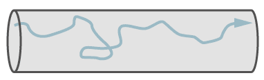
Path of a single molecule in turbulent flow.
Laminar Flow
Laminar flow is defined as a parallel flow of molcules in a pipe, whereby the transverse distribution of the speed of the molecules is parabolic.
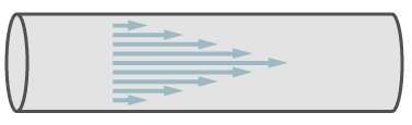
Path of molecules in laminar flow.
In the figure, the arrows symbolise the speed of the molecules. In the center of the pipe the speed is a maximum and it decreases towards the walls of the pipe.
The most wellknown formula for laminar flow is from Poisseuille. It describes the laminar flow through a straight tubulation with circular cross-section.
If one assumes that the geometry dimensions of a leak do not change during the period of measurement, the constants of the Poiseuille formula can be combined in one constant K:
Where K contains the following constants:
We can now see from this formula some properties of laminar flow: When the pressure difference across a leak changes, the leakrate changes with the square of the pressure according to the following formula:
From this we conclude that with increasing pressure in an object under leaktest a drastic increase of sensitivity can be achieved. On large containers which are filled with a search gas (for example Helium) to make a sniffer-test, a cost reduction can be achieved by increasing the inner total pressure, but reducing the concentration of the test gas. Of course the safety conditions for filling containers with pressurised gas must be followed.
Calculation of an example
An interesting example is calculated below, namely the difference in leakrate at the sniffer test, compared to a vacuum test. The leak geometry and the gas stay unchanged, also the pressure difference is 1 bar in both conditions. The difference is only: At the sniffer test the pressure conditions are 2 bar inner pressure against 1 bar (absolute) outer pressure, and at the vacuum test the outer pressure is 1 bar (atmosphere) and the inner pressure is zero bar (actually it is not zero. But for the calculation a 1/1000th of a bar is nearly zero).
| Vacuumtest |
|
| Sniffertest |
|
The leakrate at the sniffer-test is three times larger than at the vacuum-test, even if it looks like the same pressure conditions.
When the type of gas changes, the leakrate changes in inverse proportion to the dynamic viscosities of the gases.
Viscosity of some gases
As one can see, the difference of viscosity between gases is not so large, all are in the same order of magnitude.
Conversion of helium leak rate at laminar flow to leak rates of other gases
As can be seen from this table, the difference of leak rate of air is only 7.7% than helium, smaller than the accuracy of a helium-leakdetector. If we consider a leaktest with a helium/air mixture under laminar flow conditions, then the measured helium leakrate can be regarded as the same as the air leakrate. For example, in a test carried out with a 10% Helium / 90% Air mixture, the measured Helium leakrate is 10% of the total leakrate, which from the above table is:
(0.9 x 1.077) + (0.1 x 1) = 1.069
This shows an error of 6.9% taking the viscosity of air a 1.
Molecular Flow
Molecular flow exists in small leaks and at low pressures. At molecular flow each molecule travels independently of other molecules. The mean free path is larger than the diameter of the leak capillary. Therefore it is possible, that a single molecule travels against the general flow direction, because molecules do not collide with each other, but only with the walls. Despite this fact, the general flow is in direction of the lower pressure. At molecular flow the molecules follow the partial pressure down gradient.
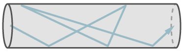
The figure shows the flow of a single molecule through a leak at molecular flow.
The formula of Knudsen for the leak rate at molecular flow is:
From the Knudsen´s formula one can see that contrary to the laminar flow, the leakrate follows linear proportion to pressure difference. To calculate a leakrate after a pressure change, the following formula is valid:
The dependency of the leakrate on molecular flow in relation to the type of gas, follows inverse proportion to the square root of the relative mass of molecules. Contrary to the laminar flow, a change of gas can make larger differences in leakrate (at constant pressure difference), as shown in the next formula:
Conversion of helium leak rate to air leak rate
The above formula with the relative masses of air and helium
at equal conditions of pressure and temperature
The air leak rate for molecular flow is a factor of 2.7 smaller than the helium leak rate. Data sheets of helium leak detectors often mention the equivalent air leakrate as well as the smallest detectable helium leak rate. This can be misinterpreted since the factor is only valid for molecular flow and not for the total range of measurement. Modern helium leak detectors can measure leakrates millions of times larger than in molecular flow. In conclusion, a helium leakdetector cannot measure air leakrates.
Conversion from weight leak rate to volume leak rate
In vacuum technology, the leak rate in general is described as volume leak rate (mbar.l/s). But there are industries which define the leak rates in loss of weight per year (g/a). The following example shows the conversion from loss of weight to volume leak rate (for constant pressure and temperature). Change to a different type of gas is also considered.
In an example from the refrigerator industry, the calculation for molecular flow leak rate becomes clear. Let us assume, that a refigerator manufacturer wants to check his products for a leakrate equal to or less than 0.01 g loss of the gas (R-12) per year. The correspondig volume leak rate is calculated via the mol:.
The relative mass of an R-12 refrigerant molecule is 121.
121 g of R-12 corresponds to 22.414 litre of gas at 1013 mbar und 00C, so that 0.01 gm R-12 = 1.85.10-3 bar.l that is 1.85 mbar.l R-12 per year.
1 year has 3.1536 . 107 seconds, then the R-12 volume leak rate is:
But this is not quite correct, because the mol is specified for the conditions of 0°C and 1.013 bar. The test takes place at room temperature, say 20°C. So we have to correct this result according to Charles´ Law (the pressure stays constant at both tests):
At molecular flow, when pressure and temperature stay constant, the corresponding helium leak rate is calculated as follows:
We remember: The dependency of the leak rate at molecular flow in relation to the type of gas, is inversely proportional to the square root of the relative mass of molecules.
This example is rarely used in practice. It was only chosen as a case of molecular flow. It shows that the helium leak rate in this case is factor 5.7 times higher than the R-12 leakrate. In practice, the required leak rates for refrigerators are in the range of 1 to 5 gm per year. These leakrates are already in the range of transition or laminar flow.
Conversion of helium leak rates at molecular flow to other gases
Note that the leak rate in molecular flow varies as the cube of diameter, whereas in laminar flow it varies as the fourth power. The leak rate for molecular flow in relation to the type of gas is inversely proportional to the square root of the relative mass of molecules (see formula of Knudsen).
Transition flow
There is a gradual transition from molecular to laminar flow which can be interpreted as both flows are present simultaneously or: at the entrance of the leak the flow is laminar which gradually changes, till at the end of the leak it is molecular flow.
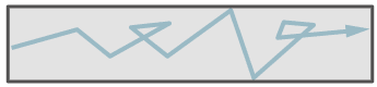
The path of one molecule in transition flow. It shows collitions with the wall and with other molecules.
The mathematical description of this condition is difficult. There are some formulae available, all of them have some restrictions. The most simple formula is from Burrow. He combined the formulae for laminar and molecular flow.
This formula can be used for rough calculations, if one takes the geometrical dimensions of an idealized leak capillary with round cross section and length much longer than diameter. One has to estimate, if molecular or laminar flow predominates and use the formula of Poisseuille or Knudsen, to calculate the dimension of the idealized leak.
The Response Time
The response times mentioned on datasheets and specifications of leak detectors are the individual response times of the leak detectors without any test piece connected, or with just the reference leak connected and are valid only for leaktests with test pieces with very small volumes. The response time of a test arrangement is given by the volume divided by the effective pumping speed of the used pumps:
The following formula describes the increase of the leak rate signal:
and the following formula describes the decrease of the signal:
Example: Integral leak test on a heat-exchanger
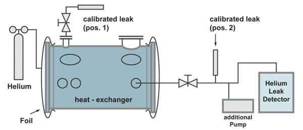
The effective pumping speed is the speed at the flange A of the heat exchanger (total pumping speed of the two pumps, reduced by the flow resistance of the pumping line).
The response time in this case is:
For the leak rate signal to reach almost its end value, a waiting time of 5 time constants is recommended. (see the following table). Therefore, after the volume under the foils is filled with 100% helium, a waiting time of around 18 minutes and 23 seconds is necessary, before the leak rate reading can be taken.
The size of the leak rate signal after tn time constants in %
The calibrated leak at position 2 is positioned before the pumping line divides between the additional pump and the leak detector. This is necessary to have a correct calibration. Part of the helium of the calibrated leak is pumped by the additional pump as is also with helium comimg from a leak in the heat exchanger.
The calibrated leak at position 2 has the following properties:
| Advantage: | The leak detector can be calibrated without helium coming into the heat exchanger, therefore not producing a background signal and calibration can be done in a short time. |
| Disadvantage: | The responsetime can only be calculated. |
The calibrated leak at position 1 has the following properties:
| Advantage: | The time constant can be measured by an extra experiment |
| Disadvantage: | The calibration of the leakdetector takes a long time, because for the increase of the helium signal as well as for the decrease (to pump away the background helium) at least 5 timeconstants are necessary. |
Remark:
Long response times, even longer than 18 minutes in this case, do not matter for the correct test result. But to localize a leak, response times of seconds are necessary. So this example shows the importance to watch the time constant during a search gas leak test
The Diffusion of Gases
The spread of one gas into another gas is called "Diffusion". Of course diffusion happens also with fluids, but here we are interested in diffusion of gases. Under equal conditions, light gases diffuse faster than heavy gases. The diffusion of gases is inversely proportional to their relative molecular mass.
Graham's Law of diffusion of Gases
(D = Diffusion coefficient, M = relative molecular mass)
Diffusion-Coefficients of some gases
at 0°C and 101.3 kPa
[mm2/s]
Note: Helium has the largest diffusion coeffcient
Example: Diffusion of Search Gas in Air
The diffusion of one gas into another at atmospheric pressure is relatively slow (and even slower at higher pressures). This requires special attention when test pieces are filled with search gas for a sniffer test. With long tubes with closed ends, the search gas cannot bypass the air which is in the test piece as far as the end of the tube. This air cushion can remain there for some time, before it is mixed with the other gases by diffusion. A leak, which happens to be at this end of the tube, may not be detected by the sensor, which is only sensitive for the search gas.
To avoid this problem, test objects should be evacuated, prior to filling with searchgas. Not a very good vacuum is needed. The diffusion speed increases with decreasing pressure. This can be explained by the expanding mean free path and therefore less collisions. If a filling of 100% search gas is wanted, the evacuation down to a pressure of 1 to 5 mbar is good enough (1/1000 - 5/1000 of atmospheric pressure).
Permeation
Permeation is the passage of a fluid into, through and out of a solid barrier having no holes. The process involves diffusion through a solid and may involve many phenomena such as adsorption, dissociation, migration and desorption.
Permeation can have an adverse effect on helium leaktest when the leakrate specification is low and the test time long. One material needing special attention is Teflon. Helium has a high permeability through Teflon and helium leaktests on test pieces with Teflon seals are almost impossible.
Permeation does not have to be taken into consideration during routine leaktest, when the measurement occurs in too short a time to permit the influence of permeation.
It can be seen, that with Neoprene it takes about 2 hours to reach saturation, but already after 30 minutes there is a leakrate of 10-9 Pa x m3/s. The gasket dimensions used in determining the graph are:
sealing length = 25 mm
thickness = 5 mm
For a larger container with gaskets of a total length of 1 metre, these permeation rates are 2 x 10⁻⁷ Pa m3/s (2 x 10⁻⁶ mbar l/s). With natural rubber or silicon rubber the time to saturation is shorter.
Thus we learn from this that, for a vacuum leaktest helium should be sprayed on these gaskets only for a very short time.
Helium Bombing Test
The bombing test is a special leak test for small and previously hermetically sealed parts which have an internal cavity like transistors, diodes, microprocessors or small relays. It cannot be used on plastic covered semiconductors (permeation). To get helium into these test pieces which are already tight, a large quantity of parts are placed into a pressure chamber and this chamber (bomb) is filled with helium to a certain pressure.
On a leaking part, helium penetrates into it but not into leak tight parts. After a certain bombing time, the parts are placed (also in large batch) into a test chamber and this chamber (bell jar, test fixture) is evacuated by a helium leakdetector. If there is a leaking part in the batch (as indicated by the response of the leakdetector), the batch is divided and each division is retested. After several divisions, the leaking part is located.
The measured leakrate is not the real leakrate. During the bombing time, the part may be not filled to 100%, also, after taking the parts out of the bomb, there is a waiting time, until the part is being tested. During the waiting time helium is escaping already, and if the leak is large, all helium may have escaped before the part could be tested.
This shows that, with the bombing test only small leaks can be discovered. A second test for larger leaks is necessary. This second test in most cases is a bubble test. The parts are placed into a hot liquid. The air inside a leaking part expands and a bubble escapes.
The filling process of helium into a leaking part is not linear. As the pressure inside increases (i.e. the lower the differential pressure), the slower is the filling rate. So the filling rate as well as the outflow rate follow an exponential function.
The formula, which descibes this process is shown below:
(* the value, which would be measured, if the testobject would be filled with 100% He at atmospheric pressure).
This formula cannot be solved to L (the real leakrate). L can only be found by trial and error (Iteration). Therefore leakrate specifications in most cases specify the bombing time, the bombing pressure and the maximun waiting time for the quoted maximum leakrate.